
How do compensation cabinet accessories work together?
Preface
Compensation cabinets must collaboratively address three core issues: harmonic suppression, reactive power compensation, and voltage stability. Reactors, capacitors, and controllers complement each other to achieve efficient control. As a component manufacturer, we will analyze the principles of synergy and key selection factors from a production perspective.
Reactors is the Core of Harmonic Control
Our nanocrystalline reactors are formed from 0.02mm strip using a vacuum quenching process, achieving core losses of 4.3W/kg (compared to 8.6W/kg for silicon steel sheets). The seven-step air gap design ensures flux distribution unevenness of ≤3%, achieving 30dB attenuation for harmonics above the 23rd order.This reactor exhibits less than 3% performance degradation under a 150% overload condition and boasts a service life of 12 years. This design reduces system harmonic distortion from 35% to 5% and reduces transformer copper losses by 12.7 kilowatts. A 14% reactor rating model is recommended for charging pile scenarios, while a DC-resistant model is recommended for photovoltaic scenarios.
The capacitor mainly plays the role of reactive power compensation.
As a power capacitor manufacturer, we use metallized polypropylene film material with a loss factor of tanδ ≤ 0.0002. Our pre-charged capacitor bank (800 kvar) is combined with a flywheel energy storage buffer, offering a response speed of 10ms. A built-in DC blocking module disconnects the circuit within 0.1 seconds upon detecting a DC component ≥ 3V. This solution maintains a stable power factor of 0.99 under 150kW load surges, completely eliminating reactive power penalties. The capacitors withstand 130% overload current and operate stably in ambient temperatures ranging from -40°C to 85°C.
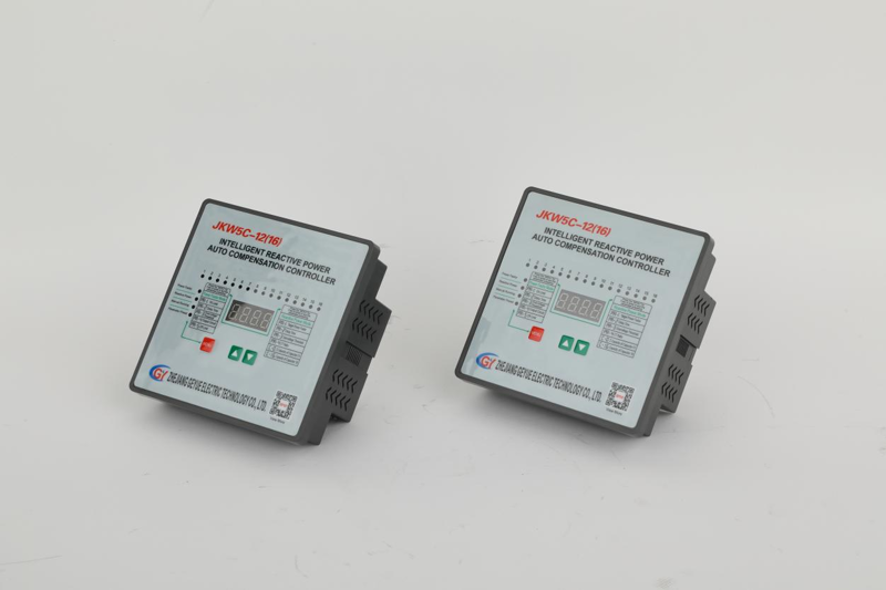
The Controller is the Key to the System.
Our quad-core DSP controller captures power data at 128 points per electrical cycle, completing harmonic FFT analysis within 5 ms. By tracking second-order derivatives of battery charge/discharge curves, it predicts reactive power demand 50ms in advance. This enables instantaneous harmonic diagnostics, proactive surge protection, and voltage stabilization during load fluctuations—forming a predictive grid fault prevention system. Using the CAN bus protocol, command transmission latency is less than 1ms. When voltage fluctuations exceed the 8% threshold, flywheel energy storage automatically coordinates to provide a 0.1-second buffer, and capacitor banks relay compensation to maintain voltage stability, reducing flicker amplitude from ±15% to ±6%, with a control accuracy of ±0.5%.
How the Accessories Work Together
When the system detects a charging pile impact, the controller identifies the sudden drop in power factor within 5ms and triggers the reactor to suppress the 23rd harmonic (attenuating it by 30dB). The capacitor bank is then dispatched within 10ms to fill the reactive power gap, and the flywheel energy storage provides a 0.1-second overload buffer. These three components work together to fill the 2000kvar reactive power gap within 50ms, keeping voltage fluctuations within ±6%.
How to Select a Reactor
The reactor's reactance must match the characteristic harmonic order. For scenarios where the 7th harmonic is dominant, select a 14% reactance model. The total number of capacitors should be configured to 1.2 times the maximum reactive power gap. An 800 kvar capacitor bank should be suitable for a 2000 kvar gap. The controller sampling rate must be ≥128 points/cycle, with a response latency ≤5ms. For heat dissipation design, reserve 0.2 m² of heat dissipation area for every 100 kvar of capacitors. When installing the reactor vertically, maintain a 10 cm air duct clearance.
Related News
- Can Self-Healing Shunt Capacitors Really Save You Money on Annual Replacement Costs?
- Are You Still Using AC Contactors and SSRs for Capacitor Switching? Here‘s Why Engineers Are Switching to Compound Switches
- Can Your Facility Still Afford to Ignore Automatic Power Factor Controllers in 2026?
- Innovative Self-Healing Shunt Capacitors: Enhancing Power Grid Efficiency and Safety
- Self-Healing Shunt Capacitors: Advancing Grid Reliability with Next-Generation Dielectric Resilience
- Global Capacitor Industry to Achieve 8.10% CAGR Through 2034
Leave me a message


 Series Three-Phase Compensation Three Phase Cylinder Self-healing Shunt Capacitor")


