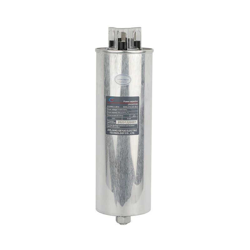
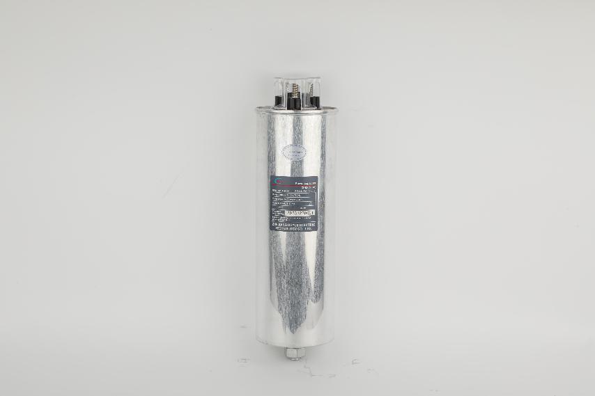
Space Magic Of Customized Capacitors: How To Fit The 0.45-30-3 Specification Into A 25Kvar Cylindrical Shell?
Preface
Modern distribution rooms and compensation cabinets are facing a contradiction between the increasing demand for reactive power compensation and insufficient installation space. Standard size power capacitors cannot adapt to limited space, and customized solutions become key. This article explores a specific case on how to achieve a capacitor with a voltage level of 0.45 kV and a three-phase capacity of 30 Kvar in a cylindrical shell with a capacity of 25 kV. The customized specification is expressed as 0.45-30-3, which requires breakthroughs in material technology and structural design.
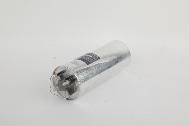
Space Dilemma and Customization Requirements for a Standard Capacitor
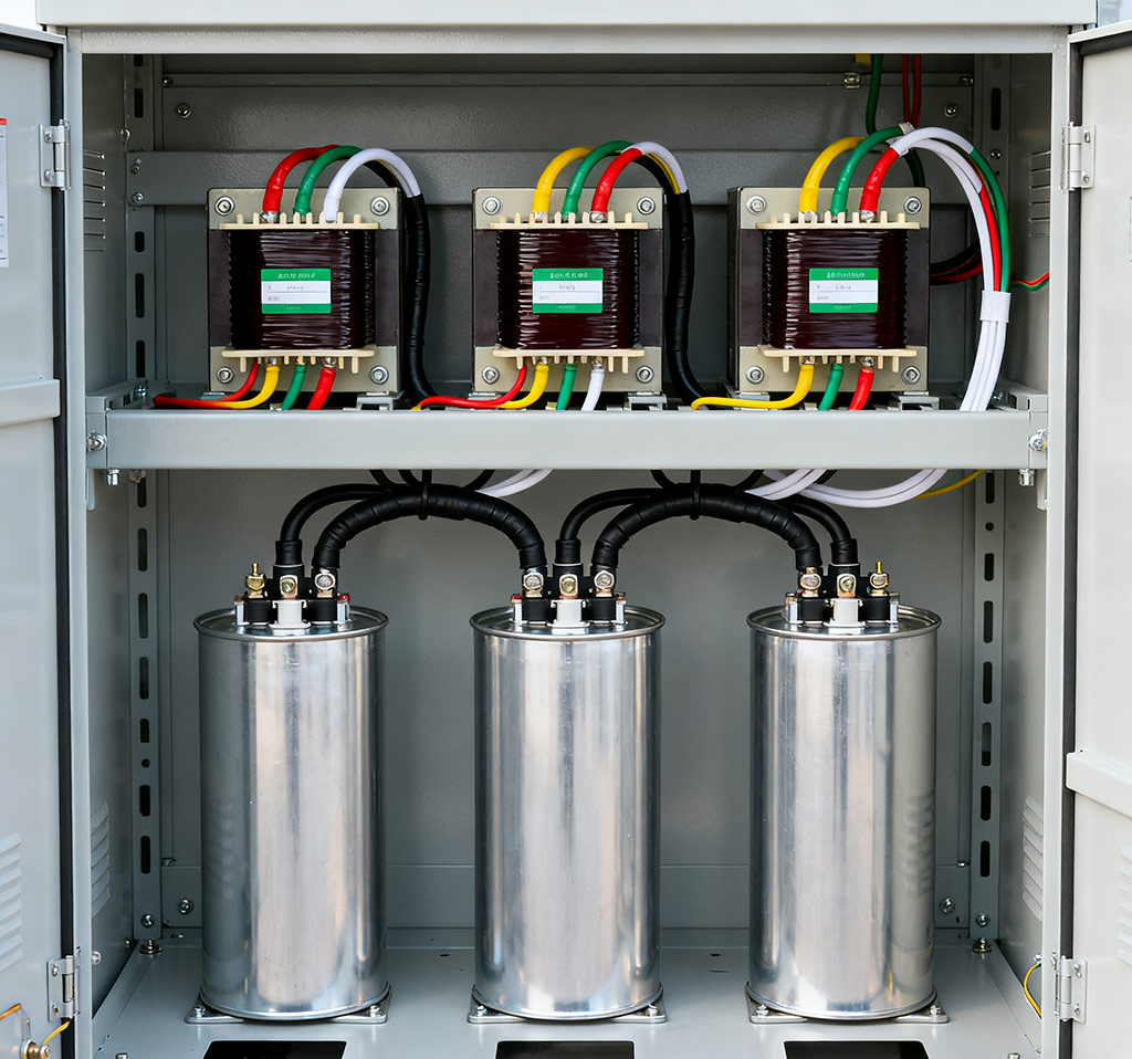
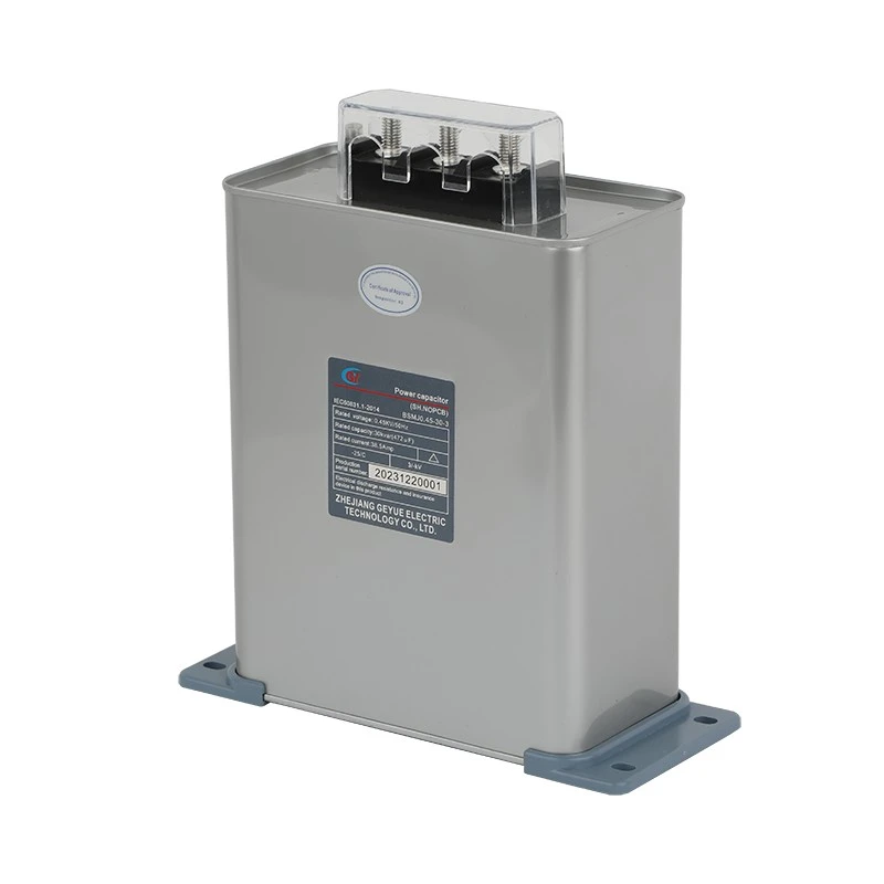
The compensation cabinet has dense internal components such as circuit breakers, contactors, reactors, controllers, etc., which occupy a large amount of space. The renovation or compact design of old cabinets leaves limited space for capacitors. Standard rectangular or square capacitor modules are difficult to adapt to irregular corners or height restricted spaces. Forced installation may lead to poor heat dissipation, difficult maintenance, and insufficient safety distance.
When standard products cannot meet spatial constraints, customizing power capacitors becomes a necessary solution. Its core advantage is form adaptability and precise performance matching. Engineers can reverse design the shape and internal structure of capacitors based on the remaining space size and electrical parameter requirements inside the cabinet. This space driven design pattern enhances the flexibility of compensation system integration.
Analysis and Technical Challenges of Specification 0.45-30-3
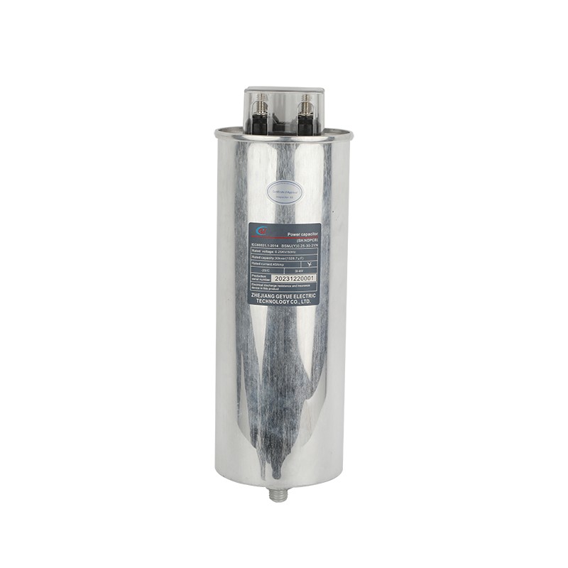
0.45 refers to the rated voltage of 0.45 kV, matched with a 380 V system. 30 refers to a single unit with a capacity of 30 Kvar, which determines the reactive power compensation capability. 3 refers to a three-phase integrated design with three capacitor units, integrated packaging, simplified wiring, and space saving.
The technical difficulty of using a 25Kvar shell lies in the fact that accommodating a 30Kvar capacity with a 25Kvar shell means that the volume remains unchanged, the capacity increases by 20%, and the power density significantly increases, which puts higher requirements on material heat dissipation and insulation. The increase in internal losses leads to an increase in thermal management pressure, and heat dissipation in limited spaces becomes a key challenge.
Breakthrough in the Design of Customized Cylindrical Capacitors
We have upgraded our dielectric material technology by using special metalized polypropylene film with a thickness controlled below 3 microns. This material has stable dielectric constant and self-healing properties. By optimizing the metal coating formula, we have achieved high square resistance characteristics, effectively reducing the loss tangent value. The film cutting and winding process is completed in a Class 10000 clean workshop to ensure the purity of the dielectric.
How to optimize the core structure? We use three key processes of high tension precision winding to ensure that each layer of film is tightly adhered. Hot pressing technology eliminates internal stress, and the end face uses vacuum gold spraying to form full contact electrodes. We design a spiral heat dissipation channel to address the heat dissipation bottleneck, forming an air convection path inside the core. At the same time, we control the amount of filling adhesive to achieve a balance between insulation and heat dissipation.
Customer Challenges and Our Solutions
We recently received a customer with a special need who is facing a typical technical challenge: after expanding the production line, the power factor drops to 0.75, and there is an urgent need to increase the reactive power compensation capacity by 180Kvar in the saturated compensation cabinet. The only available installation space is a few cylindrical areas with a diameter of 160mm and a height of 300mm - these locations were originally designed for 25Kvar power capacitors. Faced with this challenge, we quickly formed a technical team to carry out special research and development for the customized demand of 30 kilowatts for a 160 × 300mm shell. We selected a 3-micron ultra-thin metalized thin film material and redesigned the winding core structure, which increased the effective winding area by 18%; Innovatively adding axial heat dissipation grooves inside the shell and using special sealing adhesive with a thermal conductivity greater than 1.5W/mK to fill key areas; All safety components are made of high-quality products that have been independently certified. After rigorous testing, the sample fully meets the requirements of the national standard GB/T 12747, especially after 2000 hours of durability testing at 85 degrees Celsius, the capacity attenuation is less than 1%. After triggering the self-healing test 500 times, the insulation resistance still remains above 100000 megaohms, and the hottest point temperature of the temperature rise test is controlled within 65 degrees Celsius. In the end, this customized product successfully helped the customer achieve a significant benefit of increasing compensation capacity by 20% in the same space without completely changing the cabinet structure.
Conclusion: Technological Breakthroughs Achieve Spatial Optimization
Installing a 30Kvar power capacitor with a specification of 0.45-30-3 into a 25Kvar cylindrical shell is a systematic innovation in material technology, structural design, and heat dissipation solutions. Breaking through the limitations of standard products, achieving unity of performance and form. Representing the trend of power equipment towards high power density, high integration, and high reliability, customized capacitor solutions have become a key support for efficient and stable operation of power systems in the face of complex application scenarios and spatial constraints.
- Can Cylinder Self-healing Shunt Capacitor Become the Ideal Choice for the Smart Grid Era?
- Apart from Saving Electricity Costs, What Value does Low-Voltage Reactive Power Compensation Bring to Enterprises?
- How does the Temperature Dependence of a Capacitor's Capacitance Value affect the Tuning Point of a Detuned Filter Circuit?
- Is There a Non-Invasive Way to Monitor the Internal Health of Power Capacitors, Such as Their Equivalent Series Resistance (ESR)?
- What Is the Concept of "Reactive Power Banking" or "Reactive Power Dispatch" in a Smart Grid Context?
- What Are the Recycling and Disposal Plans for Self-Healing Shunt Capacitors after the End of Their Life Cycle?

