How To Achieve High-Precision Power Capacitor Filling Process?
Preface
The power capacitor filling process directly impacts equipment life and reliability. The microcrystalline wax filling process requires precise control of temperature, flow rate, and solidification environment to ensure uniform filling of the cavity with the insulating medium. This technical note, based on empirical production data, explains key process control points. As a core component in power quality management, the quality of the internal insulating medium directly determines operational stability.
Precise Control of the Filling Process
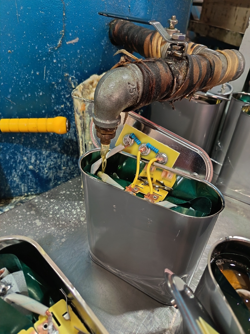
As shown in the figure, the capacitor is filled with microcrystalline wax at a constant temperature of 65°C. This wax is injected into the cavity through a metal pipe at a flow rate of 3 ml per second. The pipe is maintained at a 53-degree angle to the casing to prevent air bubbles. Before filling, the capacitor casing must be preheated to 50°C to minimize uneven wax crystallization caused by temperature differences. Operators monitor the flow meter in real time and immediately adjust the valve if the flow rate fluctuates by more than 0.5 ml per second. The filled capacitor is then placed in a -90 kPa vacuum environment for 30 seconds to eliminate any remaining bubbles. The filling pipe is wrapped with black-brown insulation material to ensure a stable wax temperature within a range of ±0.5°C. The time it takes for the blue resistor element on the yellow circuit board to be completely covered by the wax is controlled within 120 seconds. Prolonged exposure increases the risk of oxidation.
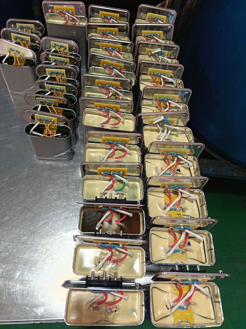
Material Property Requirements
As a capacitor manufacturer, we strictly control the quality of our microcrystalline wax raw materials. We select high-purity materials with a paraffin hydrocarbon content exceeding 92%, and a viscosity stable within the range of 85 ± 5 centipoise at 65°C. We test the dielectric strength of each batch of wax, and the breakdown voltage must be greater than or equal to 18 kV/mm. After infusion, the wax body must exhibit a thermal expansion coefficient that differs from the metal housing by less than 15% during temperature testing from -40°C to 85°C, preventing cracks from thermal cycling. As shown in Figure 2, the finished capacitor's light yellow wax body exhibits a uniform crystalline structure under X-ray, with crystal size controlled within 50 microns. The red, white and blue wires inside the power capacitor must maintain an insulation distance greater than 3 mm after wax is poured.
Quality Inspection Standards
We have established a four-step inspection process for solidified capacitors. X-ray scanning confirms porosity is less than 0.5%. A step-voltage method verifies dielectric strength is greater than 20 kilovolts per millimeter. A strain gauge array verifies shrinkage stress is less than 8 megapascals. After a -40°C freeze test, wax cores are dissected to observe crystallization. Inspectors use industrial endoscopes to check corner coverage of the casing, ensuring no exposed area exceeds 1 square millimeter.
Capacitor Type Identification Technology
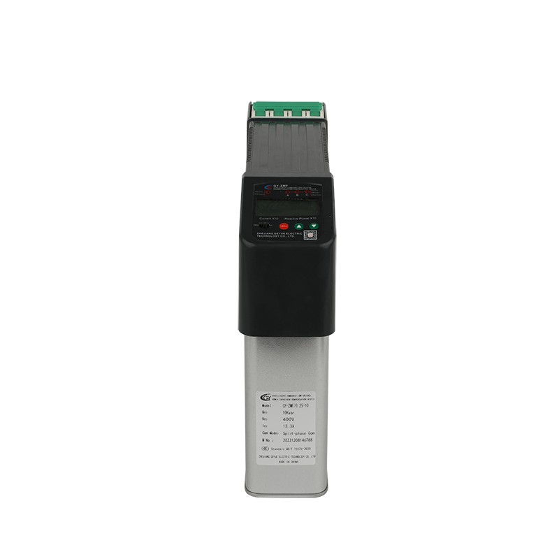
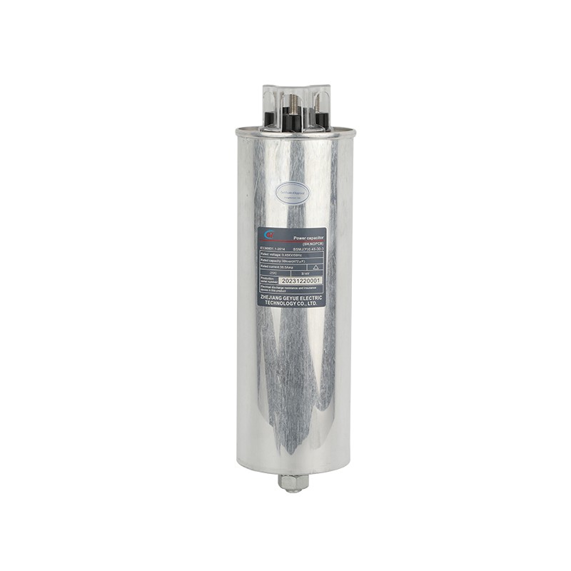
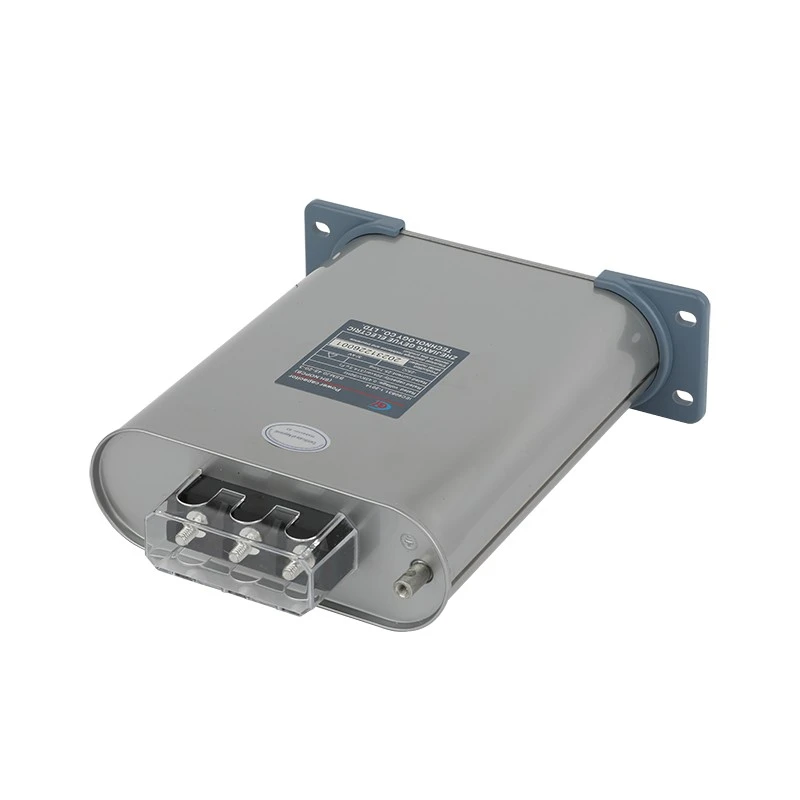
Rectangular capacitors are infused with light yellow microcrystalline wax and are suitable for power-frequency filter circuits. Oval capacitors are encapsulated with black epoxy resin and are designed for high-frequency switching power supplies. When identifying capacitors, pay attention to the color matching of the connecting wires. Red, white, and blue wires indicate general-purpose capacitors, while yellow and blue wires indicate high-temperature specialty capacitors. Users are advised to accurately select power capacitors based on the withstand voltage and capacitance values marked on the casing. Capacitors with silver-gray casings are infused with light yellow microcrystalline wax, while those with darker casings are infused with high-density epoxy resin. Wire connections use silver-plated copper connectors, and the tightening torque for the screws is controlled to 0.6 Nm.
Production Environment Control
The injection workshop maintains a constant temperature of 25±2°C and a humidity of 45%±5%. As shown in the background of Figure 1, the blue walls are coated with an anti-static coating, and the floor dust particle count is maintained at less than 100,000 per square meter. The operating table is equipped with an anti-static device, and the three-stage filtration system (100-mesh metal mesh + 5-micron ceramic membrane + 0.5-nanometer molecular sieve) is cleaned every shift. The solidification area implements a 72-hour temperature gradient: 25°C (12 hours) → 40°C (24 hours) → 60°C (12 hours) → 25°C (24 hours), maintaining a stable wax shrinkage rate of 0.7%.
Failure Prevention Measures
As a power capacitor manufacturer, we employ a triple-layered approach: The production line automatically pauses when the dielectric strength of the wax drops or the flow rate becomes abnormal; a bubble capture system triggers vacuum re-injection for bubbles exceeding 0.3 mm in diameter; and laser flaw detection is performed on all shell welds. Cracks exceeding 0.1 mm in depth are immediately scrapped. Three samples from every 1,000 units undergo 2,000-hour accelerated aging testing to monitor the change in dielectric loss factor. Yellow circuit boards undergo ion cleaning before infusion, with surface residue levels below 1.56 nanograms per square centimeter.
- Can Cylinder Self-healing Shunt Capacitor Become the Ideal Choice for the Smart Grid Era?
- Apart from Saving Electricity Costs, What Value does Low-Voltage Reactive Power Compensation Bring to Enterprises?
- How does the Temperature Dependence of a Capacitor's Capacitance Value affect the Tuning Point of a Detuned Filter Circuit?
- Is There a Non-Invasive Way to Monitor the Internal Health of Power Capacitors, Such as Their Equivalent Series Resistance (ESR)?
- What Is the Concept of "Reactive Power Banking" or "Reactive Power Dispatch" in a Smart Grid Context?
- What Are the Recycling and Disposal Plans for Self-Healing Shunt Capacitors after the End of Their Life Cycle?

