Why do Capacitor Banks of Industrial Users Frequently Fail under the Load of Frequency Converters?
In industrial power systems, frequency converters, as highly efficient and energy-saving devices, are widely used in motor control. However, their non-linear characteristics lead to increased grid harmonic pollution, which in turn causes premature failure of traditional capacitor banks. In the following text, Geyue Electric will, from the perspective of a manufacturer of low-voltage reactive power compensation equipment, systematically analyze the deep mechanism of capacitor damage under the load of frequency converters, reveal key failure modes such as harmonic resonance, current overload, and dielectric aging, and propose a comprehensive solution based on harmonic suppression and dynamic compensation, providing equipment selection and operation optimization suggestions for industrial users.
Typical Characteristics of Inverter Loads and Power Quality Issues
In modern industrial production lines, Variable Frequency Drive equipment (VFD) has become the preferred solution for motor control due to its excellent speed regulation performance and energy-saving effect. However, during the rectification and inversion processes of the inverter, non-linear currents are generated, which inject a large number of harmonic components into the power grid, especially the 5th, 7th, and other characteristic harmonics. This harmonic pollution not only causes distortion of the voltage waveform but also has complex interactions with capacitor banks in the reactive power compensation system.
The Pulse Width Modulation (PWM) waveforms generated by the frequency converter during operation contain high-frequency harmonic components that are up to several tens of times the power frequency. When these high-frequency currents pass through the capacitor, it leads to a significant increase in dielectric loss. Experimental data show that in a power grid with 30% harmonic distortion, the temperature rise of the capacitor can be more than 15°C higher than that in a pure grid environment, which directly accelerates the aging process of the insulating medium.
Analysis of the Physical Mechanism of Capacitor Damage
The failure of traditional reactive power compensation capacitors under the load of frequency converters is not caused by a single factor, but is the result of the combined action of multiple destructive mechanisms. Harmonic resonance is one of the most destructive factors. When the equivalent inductance of the system and the capacitor form a parallel resonant circuit at a specific harmonic frequency, the local current and voltage will be amplified to several times the normal value. A measured case from an automotive welding workshop shows that near the 5th harmonic resonance point, the current in the capacitor branch reached 3.2 times the rated value. This continuous overload eventually led to the bulging and bursting of the capacitor.
Dielectric polarization loss is another key failure mechanism. The high-frequency harmonics generated by the frequency converter will cause repeated polarization of the dielectric material inside the capacitor. This additional dielectric loss is converted into heat energy, causing the internal temperature of the capacitor to continuously rise. Polypropylene film, as the mainstream dielectric material, will exhibit a degradation in insulation performance at an exponential rate when operating at temperatures above 85℃. However, the ventilation design of most industrial capacitor cabinets does not take into account this additional harmonic heating factor.
The Amplification Effect of System Design and Selection Defects
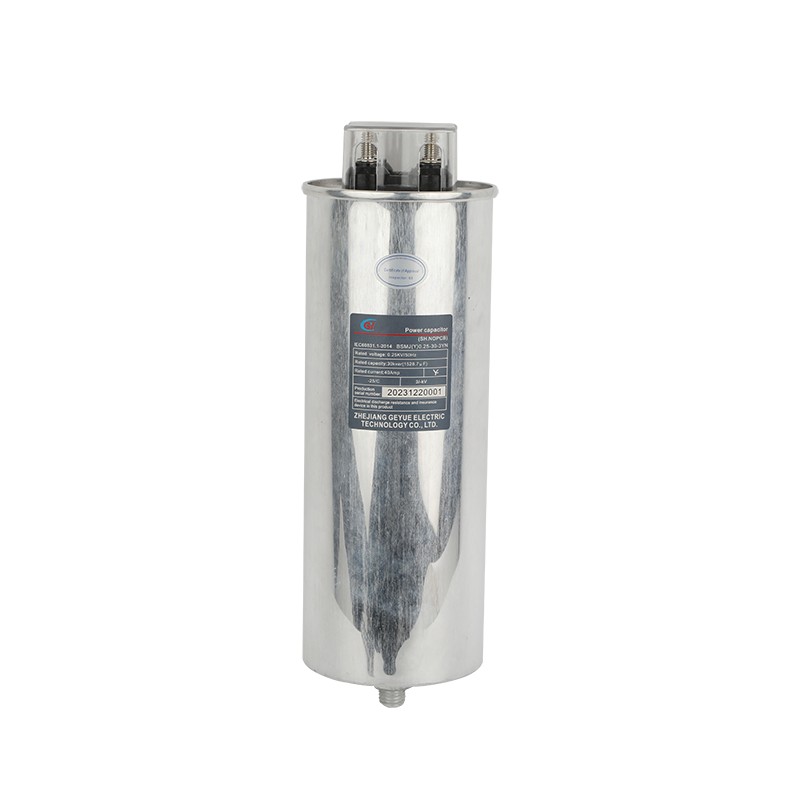
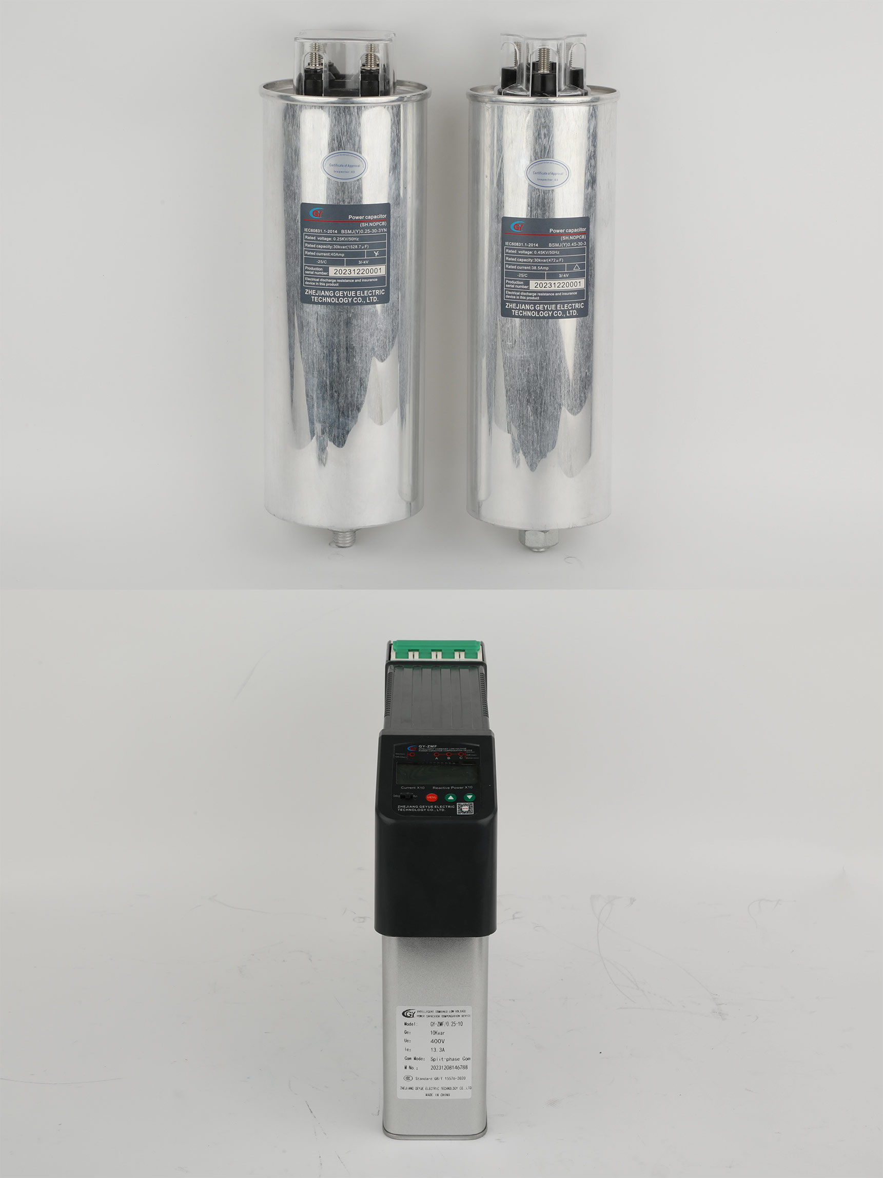
The common technical misunderstandings of industrial users when selecting capacitor banks have further exacerbated the destructive effect of the variable frequency drive load. The ordinary capacitors chosen for the sake of cost reduction only consider the operating conditions under power frequency conditions in their design standards, lacking adaptability to the high-frequency harmonic environment. In contrast, the anti-harmonic dedicated capacitors adopt thickened metallized films and special gold plating on the terminals, which can increase the high-frequency tolerance by more than three times.
The design flaws of the compensation system should also not be overlooked. In many projects, in order to save space, circuit designers directly parallelized the capacitor banks on the bus line containing a large number of frequency converters without setting up the necessary harmonic filtering branches. Even more seriously, some systems adopt a fixed compensation method. When the production line operates at light load, the capacitor capacity is excessive, and the system's capacitive impedance decreases, which instead aggravates the harmonic amplification effect. The fault analysis report of a chemical factory pointed out that during the night shift with low load, the probability of capacitor damage is 4.7 times that of normal production periods.
The Technical Path of the Comprehensive Solution
To solve the problem of capacitor damage under the load of the frequency converter, a multi-level protection system including harmonic control and intelligent compensation needs to be established. The Active Power Filter (APF) serves as the core control device, which can detect and counteract the harmonic current generated by the frequency converter in real time, and keep the Total Harmonic Distortion rate (THD) of the power grid within the safe threshold of 5%. Compared with the passive LC filter, APF has the adaptive tuning characteristic and can automatically track the changes in the harmonic spectrum of the frequency converter.
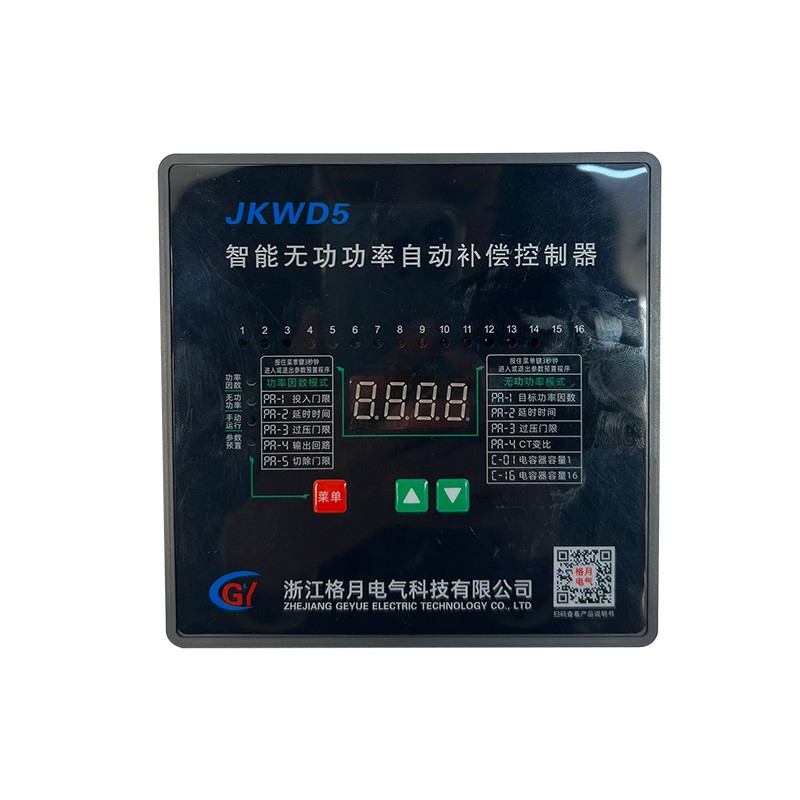
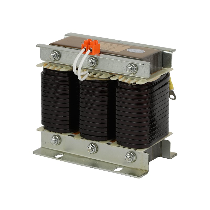
In the reactive power compensation architecture, the combined solution of anti-harmonic capacitors and dynamic tuning reactors has significant advantages. The tuning reactor precisely matches the parameters of the capacitor bank, forming a high-impedance characteristic in the main harmonic frequency band, effectively suppressing resonant current. A case study of the transformation of a steel mill's rolling machine production line shows that after installing a tuning reactor with an 7% reactance rate, the failure rate of capacitors decreased from an annual average of 12 times to 0 times, and the investment return period was less than 8 months.
Engineering Implementations and Operation &Maintenance Optimization Strategies
The successful system transformation begins with precise power quality diagnosis. Through continuous monitoring for at least 72 hours, key data such as the harmonic spectrum and reactive power fluctuations of the inverter under different operating conditions are obtained, providing a basis for scheme design. Special attention should be paid to the actual current value at the capacitor terminals. Due to the frequency response limitations of conventional current transformers, the actual impact of high-frequency harmonic currents may be severely underestimated.
Temperature monitoring during the operation phase is of utmost importance. Infrared temperature measurement points are installed in the capacitor cabinet to monitor the temperature changes of the core heating areas in real time. Practice has shown that when the temperature of the capacitor housing exceeds 65℃, its service life will be shortened to 30% of the normal value. The intelligent operation and maintenance system can predict potential resonance risks by analyzing temperature trends in advance.
The essence of the frequent damage of capacitors caused by the load of frequency converters lies in the incompatibility crisis between the traditional reactive power compensation system and the power electronic loads. Geyue Electric’s kind reminder: Solving this problem requires not only hardware upgrades such as anti-harmonic capacitors, but also the establishment of a complete technical system including harmonic control, dynamic compensation, and intelligent monitoring. Geyue Electric suggests that industrial users, in new or renovation projects, should preferentially choose full solution suppliers like our company that have harmonic immunity capabilities, so as to truly increase the design life of the reactive power compensation system to more than 10 years, providing a reliable guarantee for continuous production. If you happen to have an industrial reactive power compensation system project under construction, please consult our chief electrical engineer by sending an email to info@gyele.com.cn.
- Can Cylinder Self-healing Shunt Capacitor Become the Ideal Choice for the Smart Grid Era?
- Apart from Saving Electricity Costs, What Value does Low-Voltage Reactive Power Compensation Bring to Enterprises?
- How does the Temperature Dependence of a Capacitor's Capacitance Value affect the Tuning Point of a Detuned Filter Circuit?
- Is There a Non-Invasive Way to Monitor the Internal Health of Power Capacitors, Such as Their Equivalent Series Resistance (ESR)?
- What Is the Concept of "Reactive Power Banking" or "Reactive Power Dispatch" in a Smart Grid Context?
- What Are the Recycling and Disposal Plans for Self-Healing Shunt Capacitors after the End of Their Life Cycle?

