Are Your PFC Capacitors Safe? 5 Overheating Warning Signs You Can’t Ignore
A fire caused by overheating of a PFC capacitor will cause huge losses to the industrial power distribution system. Based on a library of tens of thousands of fault cases, Geyue Electric has summarized five overheating signals that must be intervened immediately in industrial low-voltage reactive power compensation scenarios, helping your enterprise avoid unexpected losses of more than six figures.
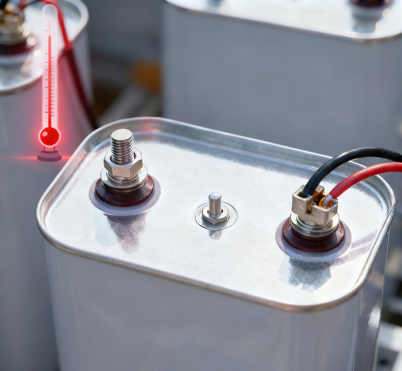
Signal 1: Abnormal increase in casing temperature (> 75℃).
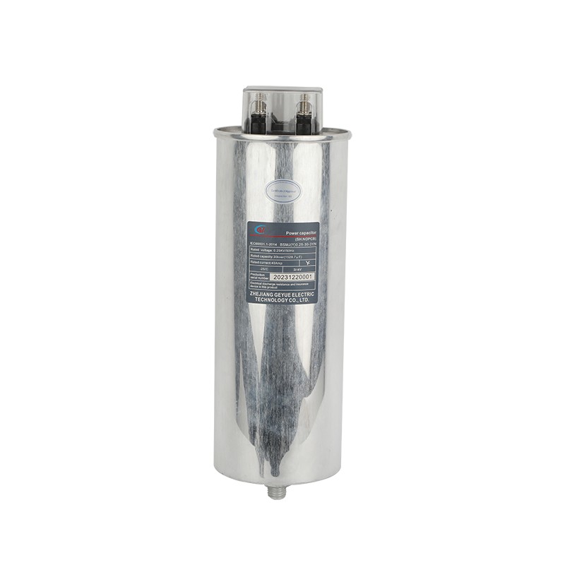
Under normal working conditions, when the ambient temperature is 40℃, the casing temperature of the PFC capacitor will not exceed 55℃. If the casing temperature of the PFC capacitor exceeds 55℃ and reaches the warning temperature range of 60 to 75℃, you need to quickly investigate the cause of the temperature rise. If the casing temperature of the PFC capacitor approaches above 75℃, you must manually intervene to immediately stop the PFC capacitor from continuing to operate. You can use an infrared thermal imager to precisely measure the temperature of the PFC capacitor's casing. You can also simply determine whether the casing is over-heated by pressing your palm against it. If your palm cannot hold against the casing for 5 seconds, we can determine that the casing is over-heated.
Signal 2: Three-phase current imbalance > 15%.
When the three-phase current imbalance in a low-voltage reactive power compensation system exceeds 15%, various hidden dangers will follow one after another, ranging from equipment damage to system collapse, such as breakdown of internal components in PFC capacitors, or the existence of sequential zero current in the system. You can calculate the unbalance degree of the three-phase current in the system using the following formula: Unbalance degree = (I_max - I_avg)/I_avg × 100%. When the three-phase current imbalance is larger than 15%, you should immediately disconnect this group of PFC capacitors and use an LCR meter to remeasure the capacitance values of each phase.
Signal 3: Discoloration or bulging of the protective coating.
According to the thermodynamic principles of materials and electrochemical laws, the discoloration and bulging of the protective coating of PFC capacitors are actually visual signals of the deterioration of the internal materials of the capacitors, directly reflecting the progressive failure of the dielectric film, metallization layer and packaging materials. The material deterioration of the capacitor protective coating is divided into three stages. The temperatures corresponding to each stage refer to the hot-spot temperatures inside the capacitor, rather than the surface temperatures of the casing. In the first stage, "Initial Oxidation", when the hot-spot temperature is between 70℃ and 90℃, the polypropylene film oxidizes and the protective coating of the capacitor slightly turns yellow. The second stage, "Mid-Term Decomposition", occurs when the maximum hot-spot temperature is between 90℃ and 110℃. The metallization layer migrates and the protective coating of the capacitor is locally browned. In the third stage, "Terminal Collapse", when the hot-spot temperature exceeds 120℃, the dielectric vaporizes and expands, causing the protective coating of the capacitor to bulge and burst. If the bulge of the capacitor is not dealt with in time, it will cause an interphase short circuit in the entire power distribution system in a few days.
Signal 4: The capacitor emits a sweet and burnt smell.
When PFC capacitors are in a state of severe overheating or about to fail, a special odor will be produced. When the hot spot temperature inside the capacitor reaches 90-100℃, the polypropylene dielectric film inside the self-healing film capacitor will initially oxidize and emit a slightly sweet honey-like taste. When the hot-spot temperature inside the capacitor reaches 110℃-130℃, dendrites grow in the metallized layer, giving off a strong caramel smell. When the hot-spot temperature inside the capacitor exceeds 130℃, the polypropylene dielectric film inside the self-healing film capacitor will undergo a thermal cracking reaction. After the dielectric carbonizes, it emits a sweet and pungent mixed smell. When you smell the above odor, please immediately wear a gas mask, cut off the power and ventilate, use an infrared thermal imager to confirm the temperature of the casing (direct contact is prohibited if it exceeds 80℃), and use an explosion-proof fan to remove the decomposed gas to avoid ignition by electric sparks.
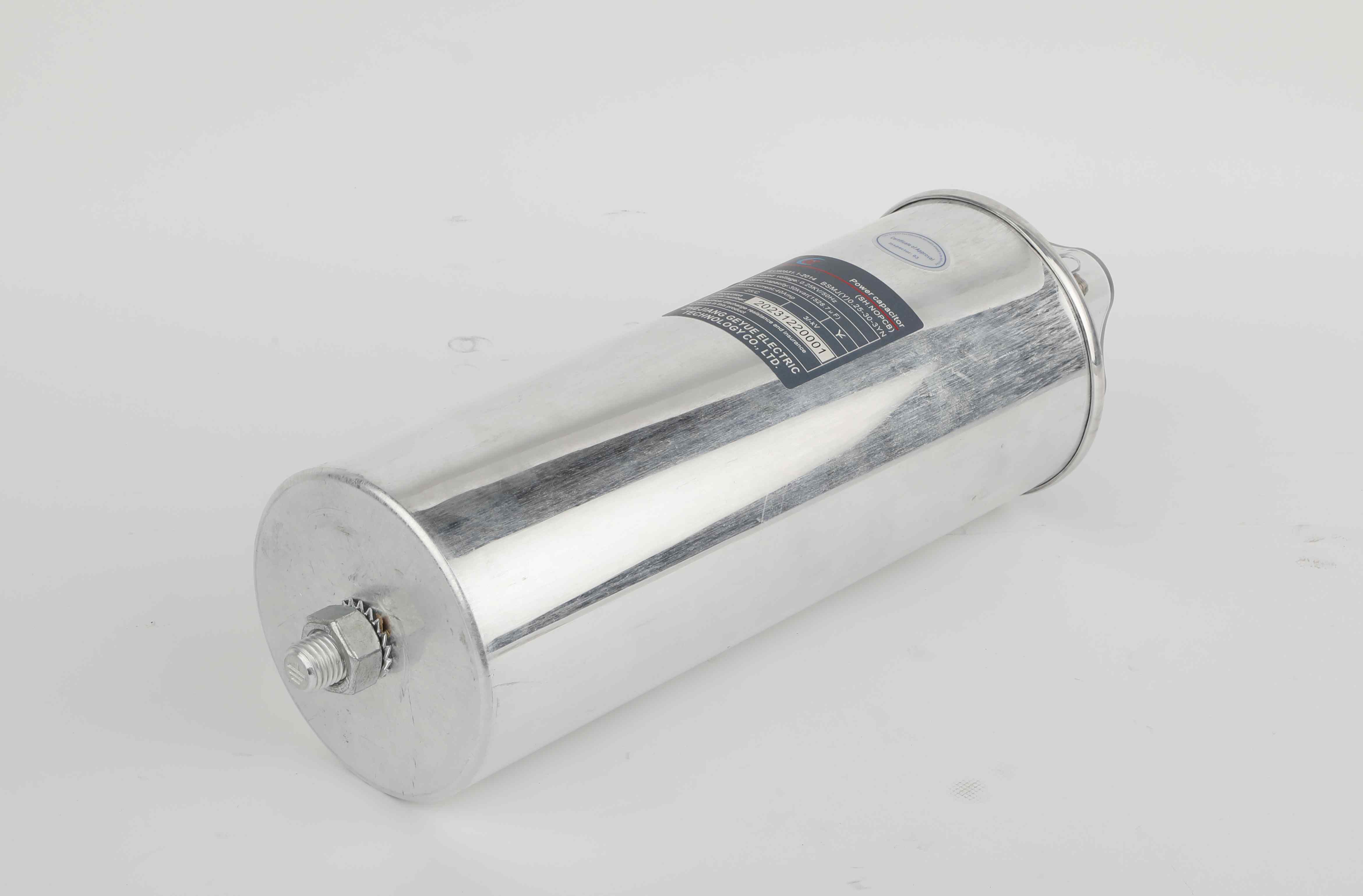
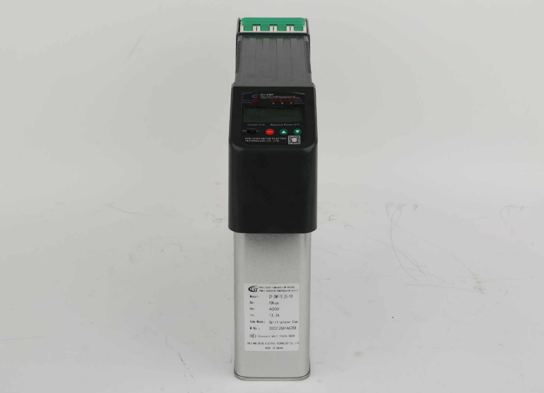
Signal 5: The early warning system of the intelligent capacitor outputs an alarm code.
If an intelligent capacitor alarm system is installed in the circuit, when the node temperature exceeds the safety threshold, the warning system will output a dedicated alarm code. You must allow the capacitor to operate at a reduced capacity within 30 minutes. When the ESR value rises by 30%, the intelligent early warning system will output a dedicated alarm code. You must immediately cut off the power supply and evacuate people within a 3-meter radius around you.
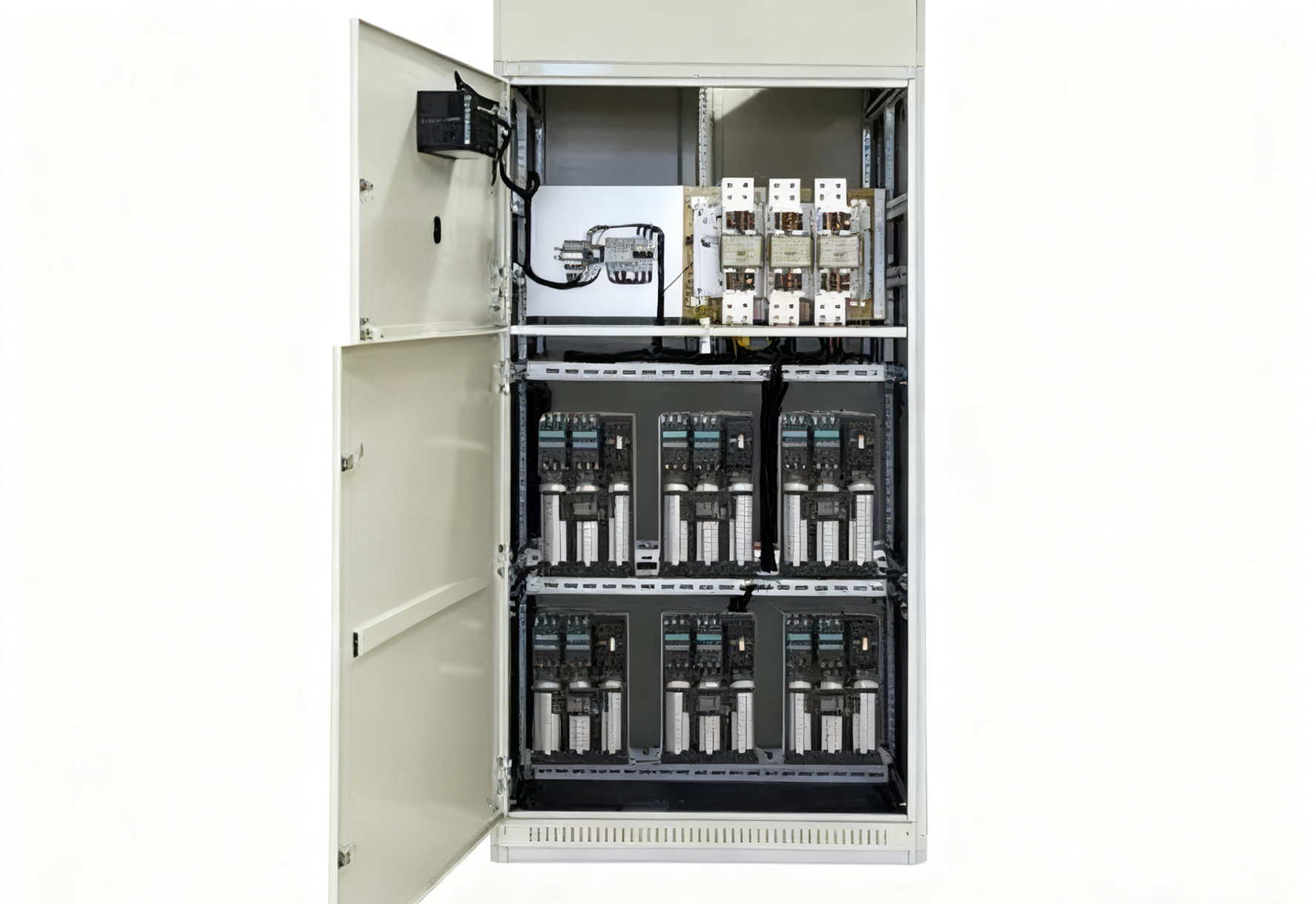
An overheated capacitor is not only a killer that brings potential hazards, but also the fuse of systemic risks. To avoid the hazards caused by overheating of capacitors, Geyue Electric sincerely suggests that industrial users use infrared fiber optic sensor dual redundancy for real-time temperature monitoring, install 7% series reactors for pre-harmonic control, and establish rapid isolation and cooling programs and other emergency plans. It's better to seize the day than to choose the right one. Now, use a thermal imager to scan your capacitor cabinet and take a look! Did you find that hot-spot temperature exceeds 65℃? Write to: info@gyele.com.cn, contact the professional team of Geyue Electric to share your worries ~
- Can Cylinder Self-healing Shunt Capacitor Become the Ideal Choice for the Smart Grid Era?
- Apart from Saving Electricity Costs, What Value does Low-Voltage Reactive Power Compensation Bring to Enterprises?
- How does the Temperature Dependence of a Capacitor's Capacitance Value affect the Tuning Point of a Detuned Filter Circuit?
- Is There a Non-Invasive Way to Monitor the Internal Health of Power Capacitors, Such as Their Equivalent Series Resistance (ESR)?
- What Is the Concept of "Reactive Power Banking" or "Reactive Power Dispatch" in a Smart Grid Context?
- What Are the Recycling and Disposal Plans for Self-Healing Shunt Capacitors after the End of Their Life Cycle?

